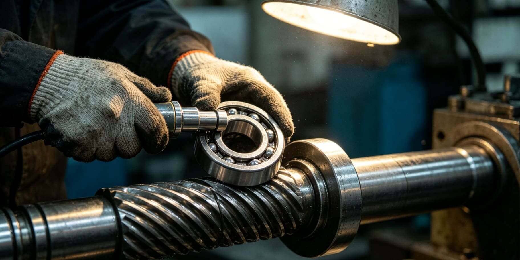
By Welink Bearing | Deep Groove Ball Bearing Installation Guide
Deep groove ball bearings are among the most widely used rolling element bearings in the world, and for good reason. They handle both radial and axial loads, run quietly at high speeds, and require minimal maintenance when properly installed. But here is the critical point: improper installation is the leading cause of premature bearing failure, accounting for over 16% of all bearing damage cases according to industry studies.
Whether you are a maintenance technician, a mechanical engineer, or a purchasing manager sourcing bearings for an OEM application, understanding the correct installation procedure is just as important as selecting the right bearing. A brand-new, precision-ground bearing can be permanently damaged within minutes if pressed, driven, or fitted incorrectly.
This guide from Welink Bearing walks you through every stage of the deep groove ball bearing installation process. From pre-installation checks to final verification, with the technical accuracy and practical detail you need to get it right the first time.
① Understanding Deep Groove Ball Bearing Structure
② Common Causes of Bearing Damage During Installation
③ Tools and Equipment You Need
④ Pre-Installation Checklist
⑤ Step-by-Step Installation Guide
• Press Fit (Interference Fit) Installation
• Thermal Expansion Method (Hot Mounting)
• Hydraulic Method
⑥ Installing Bearings into Housing (Outer Ring Fit)
⑦ Handling Sealed and Shielded Deep Groove Ball Bearings
⑧ Miniature and Small Deep Groove Ball Bearing Installation
⑨ Post-Installation Checks and Run-In
⑩ Common Mistakes to Avoid
⑪ Frequently Asked Questions
① Understanding Deep Groove Ball Bearing Structure
Before installation, you must understand what you are working with. A standard deep groove ball bearing (DGBB) consists of:
• Inner ring — fits onto the shaft (rotating or stationary)
• Outer ring — fits into the housing bore
• Ball elements — the rolling elements that carry the load
• Cage (retainer) — maintains uniform ball spacing and guides the balls
• Seals or shields (on sealed variants) — protect the interior from contaminants and retain grease
The defining feature of deep groove ball bearings is the deeply recessed, uninterrupted raceway groove in both rings. This geometry gives them their ability to handle axial loads in both directions, making them ideal for electric motors, gearboxes, agricultural machinery, automotive applications, and conveyor systems.
Key bearing dimensions you must know before installation:
| Parameter |
Description |
| d |
Bore diameter (inner ring) |
| D |
Outside diameter (outer ring) |
| B |
Bearing width |
| r |
Corner radius |
| Clearance class |
C2, CN (Normal), C3, C4 — affects interference fit selection |
Always verify the bearing designation on the outer ring before installation. For example, a 6206-2RS bearing means: 62 series, 30 mm bore, double rubber-sealed.
② Common Causes of Bearing Damage During Installation
Understanding failure modes is the first step toward preventing them. The most common installation-related damage includes:
2.1 Applying Force Through the Rolling Elements
This is the single most destructive installation error. When force is applied to the outer ring while pressing a bearing onto a shaft (or vice versa), the load path travels through the balls rather than directly through the rings. This causes brinelling, micro-indentations on the raceway surface which leads to noise, vibration, and early fatigue failure.
Rule: Always apply mounting force to the ring being fitted. If mounting on a shaft, press only on the inner ring. If mounting into a housing, press only on the outer ring.
2.2 Misalignment During Pressing
Pressing a bearing at an angle distorts the ring geometry. Even a slight tilt during installation can cause permanent out-of-roundness, compromising clearance and contact geometry.
2.3 Overheating During Thermal Mounting
Heating a bearing above 120°C (248°F) can cause metallurgical changes that reduce hardness and dimensional stability. Specifically, tempering of the bearing steel begins at approximately 150°C (302°F), leading to dimensional changes and softening of the raceway.
2.4 Contamination
Introducing dirt, metal particles, or moisture during installation is a silent killer. Even microscopic abrasive particles can cause raceway wear and increase operating noise within the first hours of operation.
2.5 Hammer Blows on the Ring Face
Striking the bearing ring directly with a steel hammer creates localized impact loads that cause indentations in both the raceway and the rolling elements. Never use a steel hammer directly on any bearing surface.
③ Tools and Equipment You Need
Essential Tools
• Bearing fitting tool kit (sleeve/drift set) — hardened steel sleeves matched to bearing bore and OD; transmit force evenly around the ring face
• Arbor press or hydraulic press — applies controlled, axially aligned force; preferred for interference fits
• Bearing heater (induction heater) — for thermal expansion mounting; preferred for medium and large bearings
• Micrometer and bore gauge — for measuring shaft and housing fits with ±0.001 mm accuracy
• Feeler gauges — for verifying axial and radial clearance
• Surface thermometer or contact pyrometer — for monitoring bearing temperature during thermal mounting
• Clean lint-free cloths and appropriate solvents — for cleaning shaft and housing surfaces
• Torque wrench — for tightening lock nuts and end caps to specification
Optional but Recommended
• SKF TMFT / similar fitting tool set — for cold press mounting of small to medium bearings
• Oil bath or hot plate — alternative to induction heater for thermal mounting
• Alignment laser or dial indicator — for verifying shaft and housing concentricity post-installation
What NOT to Use
• Steel hammers (direct contact with ring)
• Improvised drift pins or bolts as pressing tools
• Open flame (torch) for bearing heating
• Standard electric ovens without temperature control
④ Pre-Installation Checklist
Do not rush this stage. Pre-installation preparation directly determines bearing life.
4.1 Inspect the Bearing
• Remove the bearing from its packaging only immediately before installation
• Inspect for visible damage: corrosion, dents, scratches on raceways or rolling elements
• Do not remove factory-applied preservative oil from unsealed bearings. It is compatible with most lubricants and acts as initial protection
• Do not wash sealed or shielded bearings (2RS, 2Z types), they are pre-greased at the factory
4.2 Measure the Shaft and Housing
Proper fits are essential. Deep groove ball bearings are manufactured to tight tolerances, and the interference or clearance fit between the bearing rings and their mating components directly affects internal clearance and load distribution.
Shaft fit guidelines (inner ring):
| Application Type |
Recommended Shaft Tolerance |
| Rotating inner ring, light to normal load |
k5, m5 |
| Rotating inner ring, heavy or shock load |
n6, p6 |
| Stationary inner ring (outer ring rotates) |
g6, h6 |
Housing fit guidelines (outer ring):
| Application Type |
Recommended Housing Tolerance |
| Rotating outer ring |
M7, N7 |
| Stationary outer ring, normal load |
H7, J7 |
| Stationary outer ring, easy axial displacement needed |
G7 |
Measure the shaft diameter at multiple points across the fit length using a calibrated micrometer. Measure the housing bore using a bore gauge. The difference must fall within the specified tolerance range.
4.3 Clean and Prepare Mating Surfaces
• Clean the shaft and housing bore with an appropriate solvent (e.g., mineral spirits, isopropyl alcohol)
• Remove all burrs, nicks, and corrosion with a fine oilstone or emery cloth, always finish with longitudinal strokes to avoid circumferential scratches
• Check shaft and housing for roundness and cylindricity using a dial indicator
• Apply a thin film of clean bearing oil or anti-fretting compound to the shaft journal and housing bore to ease assembly and prevent fretting corrosion
4.4 Verify Bearing Clearance Class
Deep groove ball bearings are produced in multiple internal clearance classes (C2 through C4). The standard (Normal/CN) clearance is appropriate for most applications. However:
• C3 or C4 clearance is recommended when significant temperature differentials between the inner and outer ring are expected (e.g., electric motors running hot)
• C2 (tighter than normal) is used in precision applications requiring low noise and vibration
Mounting a bearing with the wrong clearance class for the fit condition can result in either excessive preload (causing overheating and fatigue) or excessive play (causing noise and reduced load capacity).
⑤ Step-by-Step Installation Guide
Method A: Cold Press Fitting (Interference Fit — Inner Ring on Shaft)
This method is suitable for bearings with small to medium bore sizes (typically up to 80 mm) where the interference fit is not excessive.
Step 1: Assemble your tools
Select a fitting sleeve with an inner diameter matching the shaft and an outer diameter not exceeding the inner ring raceway shoulder. The sleeve must contact only the inner ring face, never the cage, seals, or outer ring.
Step 2: Position the bearing
Align the bearing squarely with the shaft. Start the bearing by hand. If it does not start straight, do not force it. Recheck alignment.
Step 3: Apply force using a press
Place the fitting sleeve against the inner ring face. Using an arbor press or hydraulic press, apply slow, steady, axially aligned force. Never use impact force for tight interference fits.
Step 4: Drive the bearing to its final seat
The bearing is correctly seated when it contacts the shaft shoulder (or any abutment designed to locate it). Listen and feel for a change in resistance, the force required increases sharply once the ring is fully seated.
Step 5: Verify seating
Check with a feeler gauge that there is no gap between the inner ring face and the shaft shoulder. A gap indicates the bearing has not been driven fully home, which will cause axial movement in service.
Method B: Thermal Expansion Mounting (Hot Mounting)
This is the recommended method for medium to large bearings (bore ≥ 50 mm) or any bearing with a heavy interference fit, as it reduces the mounting force required and eliminates the risk of pressing through the rolling elements.
Principle: Heating the bearing inner ring causes it to expand. When hot, the bore diameter increases sufficiently to slip easily onto the shaft. As it cools, it contracts and grips the shaft with the designed interference.
Step 1: Calculate required temperature
The required temperature rise can be estimated using:
ΔT = (Δd / (α × d)) + 50°C safety margin
Where:
• Δd = required interference (mm)
• α = coefficient of thermal expansion for bearing steel ≈ 11 × 10⁻⁶ per °C
• d = bore diameter (mm)
• The +50°C safety margin ensures the bearing slips on without binding
In practice, heating to 80–100°C above ambient is sufficient for most interference fits. Never exceed 120°C.
Step 2: Heat the bearing
Use an induction bearing heater (strongly preferred) or a thermostatically controlled oil bath set to the required temperature. Induction heaters heat evenly, quickly, and safely, and most include a demagnetization cycle, important because magnetized bearings attract metallic wear particles during operation.
If using an oil bath, use a clean, high-flash-point oil (flash point >250°C) and suspend the bearing so it does not contact the bottom of the bath.
Do not use: open flames, blowtorches, or electric hot plates without thermostatic control.
Step 3: Handle and mount quickly
Use insulated gloves. Have everything positioned before you remove the bearing from the heater. Slide the hot bearing onto the shaft with a smooth, continuous motion. Push it firmly against the locating shoulder while holding it in position.
Step 4: Secure and allow to cool
Use an end cap, lock nut, or axial fixture to hold the bearing against the shoulder as it cools, thermal contraction can pull it away from the shoulder during cooling. Once cooled to ambient temperature, the bearing is securely mounted.
Step 5: Demagnetize if required
If you used an induction heater and the model does not include automatic demagnetization, use an AC demagnetizer before placing the bearing into service.
Method C: Hydraulic Mounting (for Large Bearings with Tapered Bores)
Large deep groove ball bearings or those mounted on adapter sleeves use hydraulic pressure to expand the bore slightly during mounting.
Step 1: Apply hydraulic oil through the oil injection hole in the shaft or sleeve
Step 2: Use a hydraulic nut to simultaneously push the bearing axially up the taper
Step 3: Monitor the axial drive-up distance to control the interference achieved
Step 4: Release oil pressure only after the bearing is fully seated
This method is primarily used with shaft diameters above 200 mm and is beyond the scope of most workshop installations.
⑥ Installing Bearings into Housing (Outer Ring Fit)
When the outer ring requires a press fit into the housing:
• Use a fitting sleeve with an outer diameter matching the housing bore and an inner diameter that does not touch the inner ring
• Apply force only to the outer ring face
• For a loose-to-transition fit (sliding fit into housing), a soft-faced mallet and sleeve may be used for gentle tapping
• For a heavy interference fit into housing, press the outer ring in using a hydraulic press with a flat pressing plate
Housing mounting tip: When pressing a bearing into a blind housing bore, ensure there is a vent hole or that the speed of pressing allows air to escape, as trapped air can cause the bearing to spring back.
⑦ Handling Sealed and Shielded Deep Groove Ball Bearings
Sealed bearings (2RS rubber contact seals) and shielded bearings (2Z metal non-contact shields) require additional care:
• Never wash sealed bearings — they are factory-filled with grease and sealed for life in most applications
• Do not heat sealed bearings above 80°C — rubber seals are damaged above this temperature; for sealed bearings requiring thermal mounting, limit to 70–80°C maximum
• When pressing sealed bearings, ensure the fitting sleeve contacts only the ring land, not the seal or shield
• After installation, check that seals/shields are not displaced or folded — a displaced seal will immediately allow contaminant ingress
For shielded bearings (2Z), the shield does not contact the inner ring; it is retained by a groove in the outer ring. These can tolerate slightly higher temperatures during thermal mounting than rubber-sealed variants.
⑧ Miniature and Small Deep Groove Ball Bearing Installation
Miniature bearings (bore < 10 mm) and small deep groove ball bearings require particular care due to their low mass, tight tolerances, and delicate cage structures.
Key considerations:
• Never use a press for miniature bearings — the force required is very low, and even a small misalignment can crack the inner ring or distort the cage
• Use a precisely ground fitting pin or mandrel, and apply hand pressure only
• Clean room conditions or a clean, still environment are strongly recommended to prevent particle contamination
• Tweezers, gloves, and anti-static precautions are advisable for very small bore sizes (< 3 mm)
• Thermal mounting is generally not suitable for miniature bearings — the small mass cools so quickly that repositioning is impractical
For Welink Bearing miniature bearing series (bore range 1 mm – 9 mm), we recommend using our dedicated precision fitting pins matched to each bore size. Contact our technical team for application-specific guidance.
⑨ Post-Installation Checks and Run-In
Installation is not complete when the bearing is seated. Verification is essential.
9.1 Check Radial Internal Clearance
After mounting on a shaft with an interference fit, the internal clearance of the bearing decreases. This reduction must be within acceptable limits for the bearing to function correctly.
Use a feeler gauge inserted between the uppermost ball and the outer ring raceway (with the inner ring held fixed) to measure residual radial clearance. Compare against the values in the bearing manufacturer's clearance table for the selected fit.
9.2 Check for Smooth Rotation
Rotate the bearing by hand. It should turn smoothly with no roughness, clicking, or binding. Any irregularity indicates contamination, damage, or an excessively tight fit.
9.3 Verify Axial Location
Confirm that retaining elements — snap rings, lock nuts, end caps, or circlips are correctly seated and properly torqued. An incorrectly torqued lock nut can allow the bearing to move axially under load, causing fretting damage on the shaft.
9.4 Run-In Procedure
For critical applications, conduct a run-in under reduced load and speed before full operating conditions:
① Start at 25–30% of operating speed with no external load
② Monitor bearing temperature — it is normal for temperature to rise during the first 30–60 minutes of operation and then stabilize
③ If temperature continues to rise beyond 70–80°C (at the bearing outer ring), stop immediately and investigate
④ Gradually increase speed and load over a period of 2–4 hours until normal operating conditions are reached
9.5 Lubrication Verification (Open Bearings)
For open (non-sealed) deep groove ball bearings, verify that the correct lubricant type and quantity have been applied. Grease fill should typically be 30–50% of the free space within the bearing and housing. Over-greasing is a common cause of elevated temperature.
⑩ Common Mistakes to Avoid
| Mistake |
Consequence |
Correct Practice |
| Pressing through the rolling elements |
Brinelling of raceways; immediate noise and vibration |
Always load the ring being fitted |
| Heating above 120°C |
Metallurgical changes; loss of hardness |
Use induction heater with temperature control |
| Skipping shaft/housing measurement |
Wrong fit; loose bearing or excessive preload |
Always measure before mounting |
| Washing sealed bearings |
Grease washout; seal damage; contamination |
Never wash 2RS or 2Z bearings |
| Hammering directly on rings |
Impact indentations; cracked rings |
Use fitting sleeves and presses only |
| Mounting in contaminated area |
Abrasive particle ingress |
Clean work area and all mating surfaces |
| Ignoring clearance class |
Preload failure or excessive play |
Match clearance class to application conditions |
| Forcing a misaligned bearing |
Ring distortion; cage damage |
Restart if alignment is off; never force |
| Under- or over-greasing |
Overheating or churning losses |
Follow manufacturer fill recommendations |
| Not verifying full seating |
Axial movement in service |
Check for gap at shoulder with feeler gauge |
⑪ Frequently Asked Questions
Q: Can I reuse a deep groove ball bearing that has been removed from service?
A: Only if it has been properly inspected and shows no signs of wear, pitting, discoloration, or dimensional change. In most maintenance applications, bearing replacement is more cost-effective than reuse risk. Never reuse a bearing that showed signs of noise or vibration in service.
Q: What is the maximum safe heating temperature for a deep groove ball bearing?
A: 120°C (248°F) for standard steel bearings. For sealed bearings with rubber seals (2RS), limit heating to 80°C. Never use an open flame.
Q: How do I know if my interference fit is correct?
A: Measure the shaft OD and bearing bore ID before mounting. The shaft should be larger than the bearing bore by the specified interference amount (typically 0–25 μm for light interference fits on small bearings). Consult the ISO tolerance tables for the shaft and housing fits appropriate to your application.
Q: My bearing feels rough after installation. What went wrong?
A: Possible causes include: contamination during mounting, damage from pressing through the rolling elements, an excessively tight interference fit reducing internal clearance to zero, or a bearing that was already damaged before installation. Remove and inspect.
Q: Should I apply grease during installation?
A: For open bearings, apply grease to the shaft and housing interfaces (not in excessive amounts to the bearing interior at this stage, grease fill should be done separately). A thin oil film on the shaft journal helps prevent fretting and eases installation. For sealed/shielded bearings, do not add grease to the bearing interior.
Q: What is the difference between C3 and standard (CN) clearance?
A: C3 bearings have greater internal radial clearance than the normal (CN) class. When a bearing is mounted with an interference fit, the rings expand/contract and reduce internal clearance. C3 clearance accounts for this reduction in high-temperature or heavy interference fit applications, ensuring the bearing retains adequate clearance in service.
Q: Can I install a deep groove ball bearing with a rubber mallet?
A: Only for very light, transition fits where the bearing can be seated by gentle tapping, and only using a fitting sleeve between the mallet and the ring face. Never strike the ring directly. For interference fits, always use a press or thermal method.
Summary: Key Principles for Damage-Free Bearing Installation
① Prepare before you start — measure, clean, and verify fits before touching the bearing
② Keep the load path correct — force always goes to the ring being fitted, never through the rolling elements
③ Use the right method for the fit — cold press for small bearings, thermal mounting for medium/large, hydraulic for very large
④ Respect temperature limits — 120°C maximum for steel bearings, 80°C for sealed variants
⑤ Verify after installation — check seating, clearance, and smooth rotation before run-in
⑥ Run-in before full load — allow the bearing to reach thermal equilibrium at reduced conditions
Proper installation is an investment that pays dividends in bearing life, energy efficiency, and machine reliability. The extra 30 minutes spent measuring, preparing, and verifying can add years to a bearing's service life.
About Welink Bearing
Welink Bearing is an integrated manufacturer and trader specializing in deep groove ball bearings and miniature bearings. Our product range covers standard series (60, 62, 63), miniature series (MR, 68, 69), stainless steel variants, and application-specific configurations including high-speed, low-noise, and high-temperature designs.
We provide full technical support to OEM customers, distributors, and maintenance engineers, from bearing selection and tolerance consultation to installation guidance and failure analysis.
Technical inquiries: Contact our engineering team for application-specific installation recommendations, custom clearance specifications, or bearing selection support.
© Welink Bearing. This technical article is provided for informational purposes. Always refer to the specific bearing manufacturer's installation manual for your product series.